how to rebuild a rotory manifold on a komatsu pc35mr-2 excavator
A rebuilt rotory manifold was used on Komatsu pc35mr-2 excavator.The oil path for the engine are divided into three parts,one is oil pan and trough the oil pump to the crankshaft and from the cylinder head to the connecting rod and piston .When the fuel and air mixing in the combustion chamber,then it will be ignited into fire.And the hot igniter produce a large amount of heat energy,which would be carried away by oil in engine.And if there is some unburned gas ,the carbon deposition would be generated on the piston wall and others surfaces.
komatsu pc35mr-2 excavator-What are the tools and equipment which are needed to rebuild a rotary manifold on a Komatsu PC35MR-2 excavator?
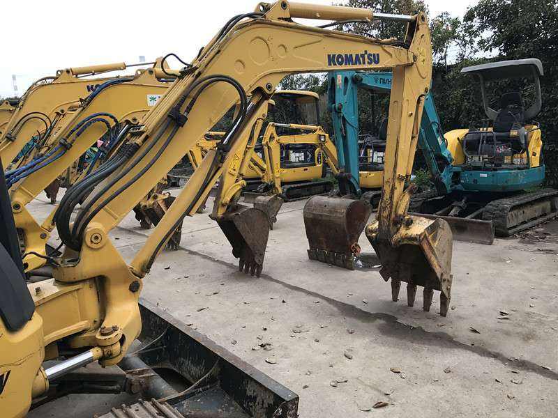
The PC35MR-2 is a machine I’m unfamiliar with, but Google suggests it is a relatively compact excavator.
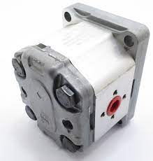
In general, the rotary manifold on an excavator is a large casting which contains a number of flanges to which hydraulic hoses are attached. It is usually connected to some form of swing drive mechanism which allows the upper part of the excavator to swivel through a range of angles.
In order to rebuild or replace this component, you will need:
A hoist capable of lifting several tons and reaching high enough, possibly with a jib or extension arm;
A number of large spanners and/or socket sets for removing nuts and bolts;
Possibly access to a workshop press or hydraulic ram for removing/replacing bearings etc.;
Possibly specialist tools for working with hydraulic pipes and hoses.
komatsu pc35mr-2 excavator-How do you run fuel lines on the manifold of a Komatsu PC35MR-2 excavator?
The fuel lines (hose) must be installed on the manifold as follows:
1. The fuel inlet hose (from the tank) has a blue tape at the end of it. This hose must be connected to the port on the left side of the manifold.
2. The fuel return hose (from the injection pump) has a red tape at the end of it. This hose must be connected to the port on the right side of the manifold.
3. The bleed hose (from pressure regulator) does not have any tape at the end of it and must be connected to the remaining port on the left side of the manifold.
komatsu pc35mr-2 excavator-What are the steps involved in rebuilding a rotary manifold on a Komatsu PC35MR-2 excavator?
This is really a question for Komatsu. They don’t sell parts to the public and they don’t allow their dealers to sell parts to the public without a signed agreement. If you are not a dealer, you would need to find one that will sell you the parts.
The steps involved in rebuilding a rotary manifold are as follows:
1. Remove the boom cylinder.
2. Remove the boom.
3. Remove the bucket cylinder.
4. Remove the bucket.
5. Remove the dipper arm cylinder.
6. Remove the dipper arm.
7. Remove the thrust bearing from the swing axle shaft (this is done by rotating it until it clears).
8. Install an alignment pin in the top of the swing axle shaft (this is done by inserting a bolt into it).
9. Remove the swing motor mounting bolts and lower swing motor off of swing stop bracket (be careful not to lose alignment pin).
10) Remove bolts that secure rotary manifold to swing gear case and remove rotary manifold from swing gear case (be careful not to lose alignment pin).
komatsu pc35mr-2 excavator-What is the torque setting for the exhaust manifold bolts on a Komatsu PC35MR-2 excavator?
Komatsu Service Manuals, Electric Wiring Diagrams and Operation & Maintenance Manuals
Komatsu PC35MR-2 Hydraulic Excavator Operation & Maintenance Manual (SEBM010905) – SEN00292-03
This service manual PDF download for the PC35MR-2 Komatsu Hydraulic Excavator has been prepared as an aid to improve the quality of repairs by giving the serviceman an accurate understanding of the product and by showing him the correct way to perform repairs and make judgements. Make sure you understand the contents of this manual and use it to full dffect at every opportunity.
This Service Manual contains detailed maintenance, service, repair and troubleshooting procedures for the Komatsu PC35MR-2 Hydraulic Excavator. The Service Manual is also referred to as the Shop Manual or Repair Manual.
Table of Content:
SAFETY INFORMATION
SAFETY PRECAUTIONS FOR HYDRAULIC EXCAVATOR
1. General safety precautions
2. Safety precautions when working on upper structure/swing frame/undercarriage/track chain
3. Safety precautions when servicing fuel system/engine air cleaner/exhaust system/cooling system/electrical system/hyd.
komatsu pc35mr-2 excavator-How to remove and install rack and pinion assembly on komatsu pc35mr-2 excavator?
1. Disconnect battery cables from battery.
2. Remove accelerator pedal, accelerator pedal position sensor and bracket.
3. Remove seat and cab floor panel (if equipped).
4. Remove access cover from right side of cab floor and disconnect harness connector.
5. Remove right front cab mounting bolt and move cab to the right to gain access to the control valve mounting plate bolts behind the column. Remove the mounting plate bolts and slide the valve off the mounting plate towards the left side of machine. Do not disconnect any hydraulic hoses from control valve at this time!
6. Remove three bolts securing pitch cylinder bracket to center frame rail, then remove bracket assembly from machine.
7. Position rack hose protective cover aside so that control valve may be moved away from frame rail but still connected to hoses.
8. Remove control levers, linkages, and brackets as required in order to separate control valves from hoses and remove valve assembly completely from machine as an assembly with all hoses still connected as one unit (Do not disconnect hoses!). Control valves are matched sets and should be reinstalled as a set only!
komatsu pc35mr-2 excavator-How to replace the front idler roller bearing on a Komatsu PC35MR-2 excavator?
The idler bearing on my Komatsu PC35MR-2 had gotten worn and the resulting slack was throwing off the tracks.
To replace the bearing you have to remove the track and then take out the idler itself. The track is held in place by a single bolt through the center of the idler and one bolt at each end of the track itself (you can see them in the picture below).
These are actually bolts with a nut welded to one side, so you need two tools to remove them: a standard wrench for loosening and an open-ended wrench for tightening. Make sure you get a good grip on the nut part of the bolt so it doesn’t turn when you try to loosen or tighten.
Once these bolts are off, you can pull out the track and then unbolt the idler from its mount. Be prepared for lots of grease (and water) to come out at this point.
The new part comes with two new bearings, but only one of them needs replacing. The trick is that they’re not installed in their seats yet, so before you install it, you have to pry out the old bearing and press in a new one:
Now all that’s left is to put everything back together!